Rectified Output Circuit Explanation with CRO Screen Graph
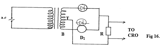
A student connected a circuit as shown in figure 16 below hoping to produce a rectified output.
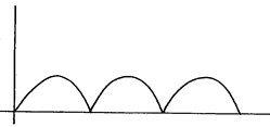
(a) Sketch the graph of the output on the CRO screen
(b) Explain how the output above is produced
0
(0 Ratings)
(a)
(b)
- During the first half –cycle D1 is forward biased while D2 is reverse biased. Hence, current takes the path A , D1 RT.
- During the next half –cycle, D2 is forward biased while D1 is reverse biased and the path of the current is BD2RT
In this thought-provoking response, the author's perspective is skillfully backed by an extensive body of comprehensive research and readily available information, offering a well-informed and compelling exploration of the subject matter.
Identify radiation B and provide an explanation for the differing deviations observed in the paths of radiations A and C as they pass through an electric field, as depicted in figure 15.
Determine the frequency of X-rays produced in an X-ray tube with a 12000V acceleration voltage, assuming full energy conversion, using Planck's constant and the charge of an electron.
Name the components labeled A and B in the X-ray tube, explain how altering the potential across P affects X-ray intensity, and describe the cause of the high temperature in the tube during operation.